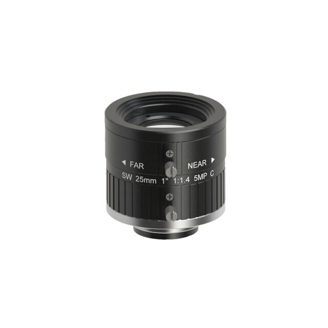
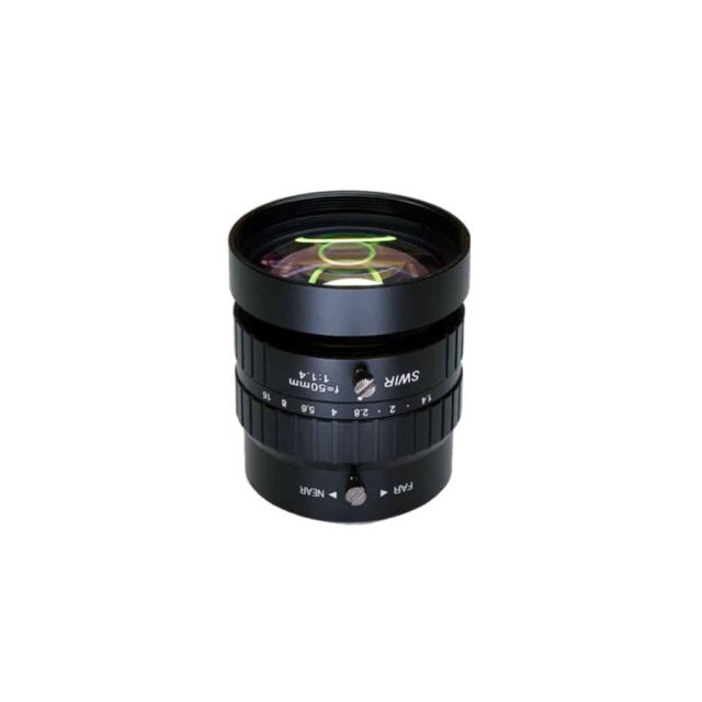
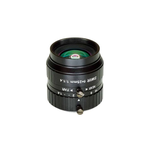
As light passes through different mediums (glass, air, water, etc.) it bends at different angles. It is common to see this when sunlight passes through prisms and produces a rainbow. Shorter wavelengths bend more than longer ones. The same problem occurs when trying to gain information and resolve details in imaging systems. Monochromatic illumination is used in imaging and machine-vision systems to avoid this problem. This involves using only a single wavelength or narrow band of the spectrum. Monochromatic lighting, such as a 660nm LED, can be used to eliminate chromatic aberrations in an imaging system. A 660nm led can virtually eliminate what is known as chromatic distortions in imaging systems.
Chromatic Aberrations
There are two basic types of chromatic aberrations: lateral color shifting and focal chromatic shift.
As you move away from the center to the edges of the picture, a lateral color shift can be observed. The spots of different wavelengths are concentric in the middle. As you move towards the corners of the image, the wavelengths separate and create a rainbow. This color separation causes a point to be imaged across a wider area. The result is a reduced contrast. This blurring is more noticeable on sensors with smaller pixels. How aberrations affect machine vision lenses provides more details about lateral color.
The Chromatic Focus Shift is the ability of the lens to focus wavelengths at the exact same distance from the lens. The best plane of focus for different wavelengths will be different. The reduced contrast is caused by this shift in focus in relation to wavelength, as the different wavelengths produce different sized spots on the image plane of the camera sensor. In the small spots in red wavelengths are shown, followed by a larger green spot and finally the largest blue spot. All colors may not be in focus at the same time. How aberrations affect machine vision lenses contains more details.
Choosing the Optimal Wavelength
Monochromatic illumination improves contrast by eliminating both chromatic focus shift and lateral aberration. This is available as LED illumination, through lasers and filters. Different wavelengths may have different MTF in a given system. The diffraction limits define the smallest theoretical spots that can be produced by a perfect optic as defined by the Airy Disk diameter, which has a wavelength (λ) dependence. See Limitations on Resolution and Contrast: The Airy Disk, for more details on the Airy Disk and diffraction limit. Using the Equation 1, one can analyze the change in spot size for both different wavelengths and different f/#s.
(1)
The Airy disk size is calculated for a range of wavelengths from Violet (405nm), to Near-Infrared (8880nm), at different f/#s. These data show that shorter wavelengths are better for theoretical performance and resolution. Understanding this is beneficial in many ways. The smaller spot sizes of shorter wavelengths allows for better use of pixels on the sensor, regardless of their size. This is particularly noticeable on sensors that have very small pixels. It also allows greater flexibility in using higher f/#s to achieve a deeper depth of field. A red LED at f/2.8 could produce a spot of 4.51mm, or a similar spot at f/4 could be generated by a blue LED. The system using blue light at f/4 will provide a greater depth of field if both options are acceptable at best focus. This could be an important requirement. Sensor relative illumination, roll off and vignetting contains more details.
Example 1: Improvement with Wavelength
The same lens and camera were used to produce both images. This produces the same field-of-view, resulting in the same spatial resolution for the object (in lp/mm). The camera uses 3.45mm pixels. The illumination is set to 660nm, respectively. The high-resolution lens was set at a higher f/# in order to reduce aberrational effects. Diffraction can then be used as the main limitation of the system. The blue circles represent the resolution limit. Note that have a marked increase in detail (approximately a 50% improvement). The contrast is higher even at lower frequencies (wider line widths).
Example 2: White Light vs. Monochromatic MTF
In a lens with the same focal length and working distance is used. It uses white light and 470nm illumination. In all the performance at Nyquist limits is 50% or less. The entire performance at the Nyquist Limit is higher than it. The performance of the central system is also higher. This increase in performance can be attributed to two factors: monochromatic illumination eliminates chromatic distortions, which allows for smaller spots. 470nm illumination also is one of the shorter wavelengths used for visible range imaging. Shorter wavelengths are able to achieve higher resolution as explained in the sections about diffraction limits and Airy Disk.
Wavelength Considerations
Changing wavelengths can cause a few problems that must be understood. The further you go into the blue spectrum, the shorter the wavelengths will be. This is true regardless of the width of the waveband. Glass materials are not good at shorter wavelengths. There are designs that work in this part of the spectrum but they can be limited and expensive due to the exotic materials required. The theoretically best performance is shown in Table 1 at 405nm violet, but many system designs are not able to perform well. The lens performance curves are a great way to determine what a lens is capable of at short wavelengths.
Example 3: Theoretical Limitations
It compares the performance of a 35mm lens with a violet (405nm wavelength) and blue (470nm). While it shows a lower diffraction, it also shows the higher performance of the 470nm wave length at all positions. This effect is enhanced when the lens is operated at its extremes for f/# or WD (detailed MTF and MTF curves).
The chromatic shift is another wavelength issue which can have a significant impact on performance. The lens’ ability to perform at high levels will be compromised as the wavelength range of the application increases. How Aberrations Impact Machine Vision Lenses provides more information on this phenomenon.
To learn more, please feel free to contact us at info@superiorcctv.com.


